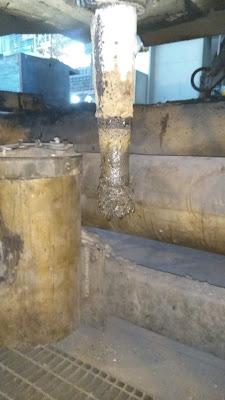
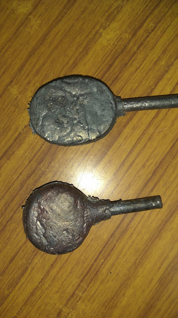
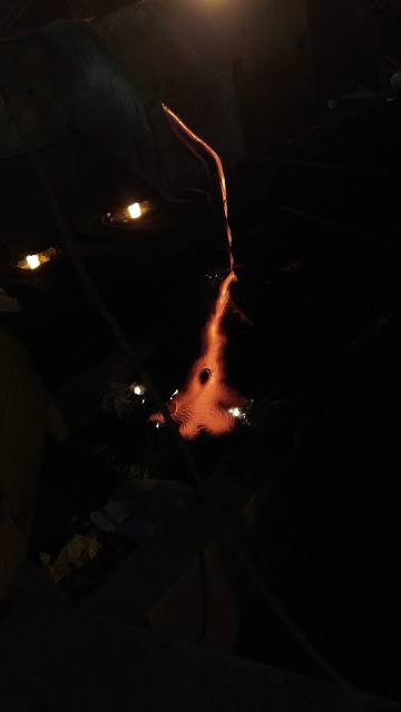
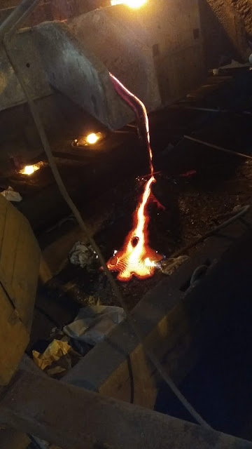
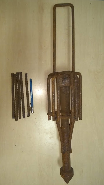
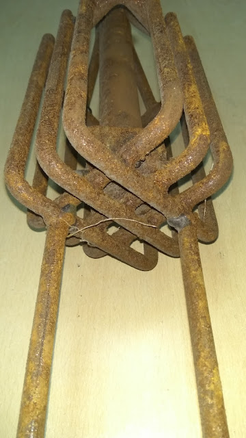
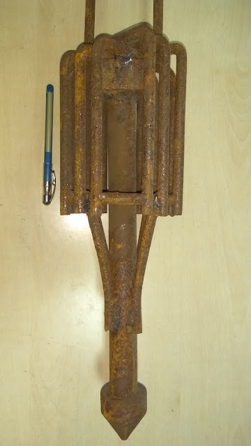
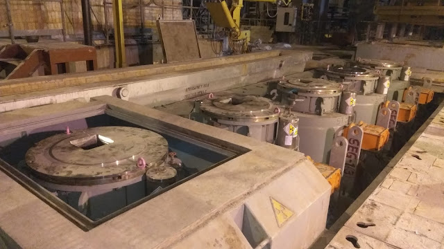
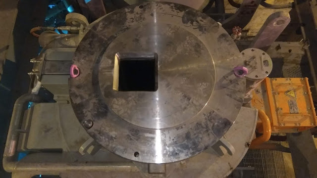
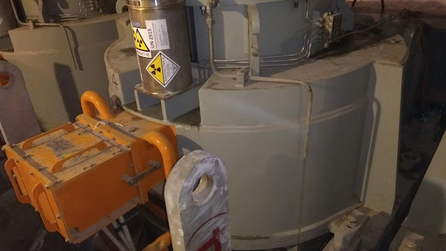
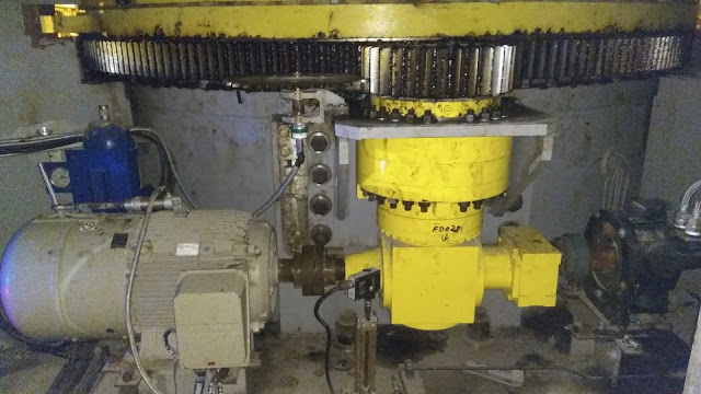
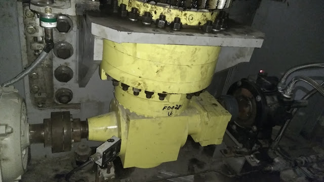
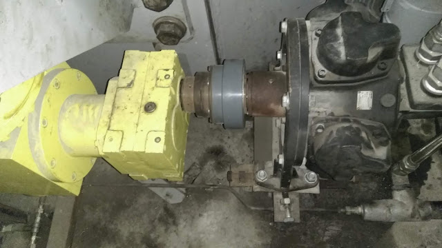
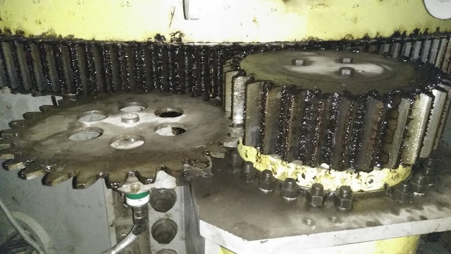
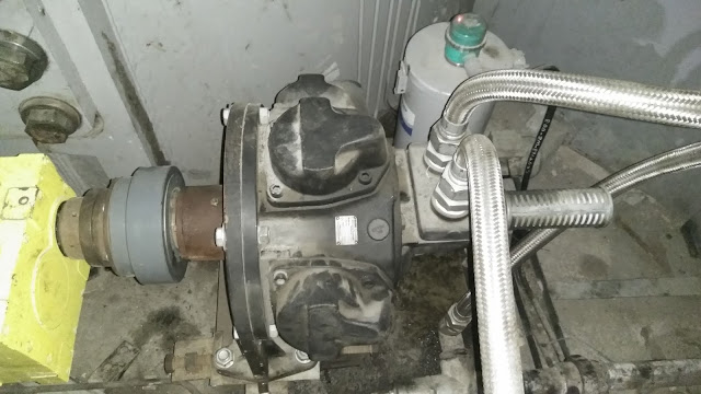
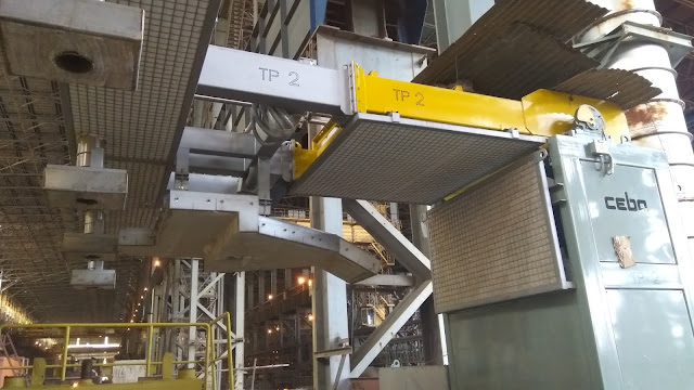
this video shows how a solid dummybar in a 5 modules caster is inserted into the mould . there are 2 limit switches and 2 striker-rods and a striker plate to help insert and withdraw dummybar either manually or automatically. these limitswitches help us ensure the physical position of the dummybar while moving. apart from this, actual movement is tracked by rotary encoders that are fixed on motors.
Monday, July 23, 2018
open casting nozzle
in open casting, top nozzle fixed at the tundish wellblock has 22mm dia, while the bottom nozzles can be changed to get desired speed.
bottom nozzles have varying dias like 15.5mm, 17mm, 18mm, 19mm, 20mm and 22mm. first one is always used at the start of casting so that the start of casting is slower, while the largest dia nozzle is used to get the maximum flowrate and hence the maximum casting speed.
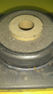
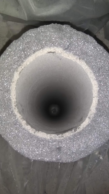
pic shows a bottom nozzle that has a dia of 17mm.
we can see the number 7 embosed on the nozzle itself so as to identify the dia of 17mm. 15.5mm dia nozzles will have 5 imprinted while 21mm dia nozzle will have 1 embosed and 19mm dia nozzle will have 9 imprinted.
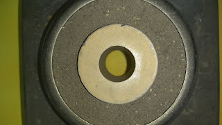
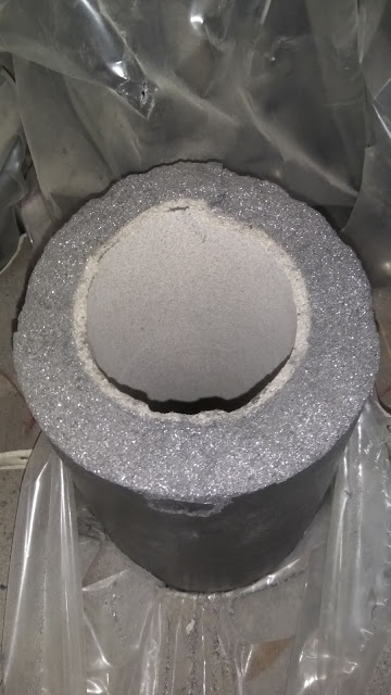
in the above pic the cream-coloured part at the center that has the bore of 17mm dia is zirconia insert which has a very very good oxidation resistance at high temperatures, strength and erosion resistance. and the gray colored granules that surround the zirconia insert are made of alumina which also has good thermal properties but not as stable as zirconia against erosion.
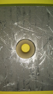
the pic below shows the surface that will mate with similar surface of top nozzle. this is the surface that normally lies facing upwards while the side shown above normally stays facing mould.
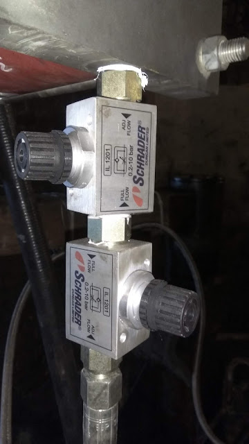
pneumatic valves in a ladle shroud manipulator
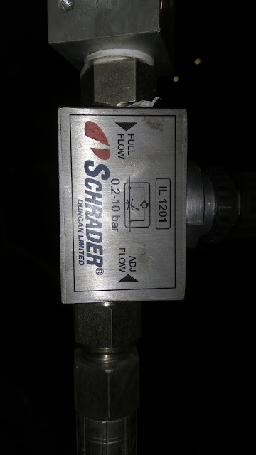
this pic above shows a pneumatic valve that is fixed in a ladle shroud manipulator mechanism. arrow marks indicate the direction(downwards) in which the flow is unhindered and the direction (upward) in which flow can be regulated.
next pic shows another valve attached just above this valve but in reversed position. bottom valve regulates the flow into the cylinder (piston side, so that lifting speed of shroud manipulator is proper), while the valve at the top bleeds the Instrument Air from the piston side of the cylinder to lower the manipulator at a controlled speed. while lowering bottom valve does not offer any resistance to the downgoing airflow. the block knob at the side of the valve body helps to regulate the flowrate of the IAir going in or out to help regulate the speed of raising or lowering the manipulator.
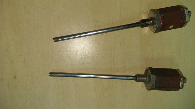
LVDT or temposonic or linear sensor
this above pic shows linear variable displacement transducers that are used in tundish slidegate cylinder pistons to track the position of the piston (and hence the position of the rigidly attached slidegate middle plate).
it is these transducers ( temposonic) that give us the feedback about the overlapping of bores of top-middle-bottom slidegate plates of tundish.
the cylinders in which these temposonics are attached have a stroke length of 90mm while the bore dia of slidegate plates is 40mm. this stroke length of more than double the bore-dia ensures perfect safety of slidegate mechanism.
to my limited knowledge, these temposonics work based on magnetostriction method where a moving magnet causes changes in current flow indicating the position of the magnet (in turn that of the piston).
MOM valve damage
mould oscillation is achieved through electro-hydraulic means in modern casters.
in the casters at my present work, these oscillator can have a frequency range of 25-300 CPM (Cycles Per Minute). the total stroke the cylinder piston is 50mm while during normal casting the range required is 8mm to 15mm maximum.
it is an easy logic that the oscillation should start at exact middle of the entire stroke; and target stroke should be distributed equally to the up and down side of this offset position of the cylinder.
it shall further be noted this offset position can be changed but should lie at the right position so that whatever oscillation is achieved should stay in line with the radius of the machine. this is necessary to avoid any external stress that may be exerted on the tender, weak shell inside the mould that may easily rupture.
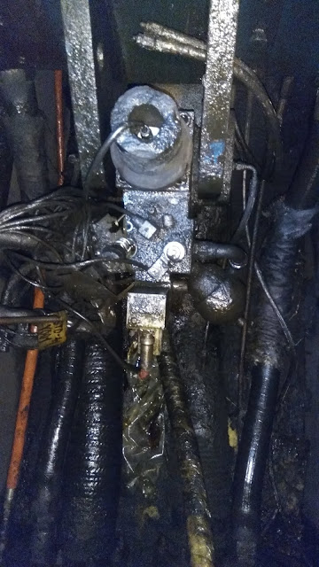
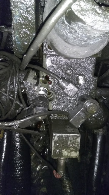
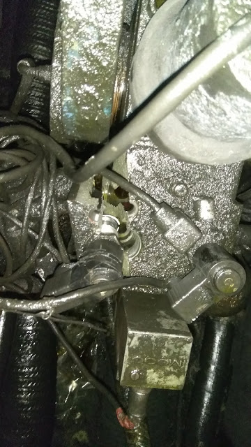
these pics show a damaged valve stand that drives the cylinder up and down.
the first pic shows the LVDT placed inside the actuator piston of the hydraulic cylinder on top portion of the entire mechanism in the top of the image. the hoses below carry mould (inlet&outlet) and spray water of zone-1. the bob like structure positioned at an angle in the mechanism is an oil accumulator that helps in fast response to compensate for pressure drop inside valve or cylinder.
in the following image, cable that is from the LVDT (temposonic) is shown inside that round protection housing. the other two blocks of the mechanism just below that round housing show the actual valve (middleblock) and below that lies the moog controller block.
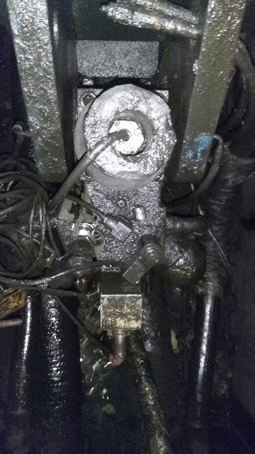
following closer image shows the same, but one can easily see the damaged valve block. this damaged was caused by excessive insertion of bottom-fed-dummybar. it travelled excessively up into the mould because of tracking failure from slipping withdrawal module motor-roll. the tracking is done using a rotary encoder attached to the motor.
it can be seen from the pics, the valve block has damaged along the ON-OFF valve connector on the left side while the right side ON-OFF valve stays intact. just above them at the middle lies one of the two pressure gauges that track the pressure built on the top side of the cylinder during oscillation. moog block makes this entire setup a SERVO VALVE whereby error tracking and correction in input command to the valve spool is done through inbuilt electronic circuitry to ensure the desired positions are achieved.
centering of SES
during casting, it is important to have the body-centre-line of the SES aligns with the body-centre-line of the mould. if this alignment is not ensured and the SES stays close to one of the four sides of the mould, then it is likely to discharge fresh metal much closure to that side of the mould.
closer position of the discharge point of SES takes a longer distance to develop the necessary shell-thickness to develop sufficient shell thickness, thereby sufficient strength to withstand the ferrostatic pressure of the liquid steel above it at any given point of the strand from meniscus.
closer side may have thinner than normal shell thickness while the far side may have thicker than normal thickness. thinner shell may not strong enough to withstand ferrostatic pressure and thicker shell may develop extra strain, thereby chances for breakout are enhanced due to misalignment.
this pic above shows an improperly aligned SES in mould during casting. it becomes the responsibility of the mould operator to correct it by CT movement of tundish which is done through hydraulic cylinders in tundish cars.
SES clean and choked
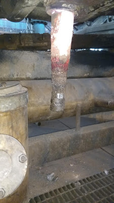
these pics show the SESs (Sub Entry Shrouds) of the same tundish, photographed immediately after end of casting from adjacent strands.
if we take a look at these 2 tundish shrouds, the easily distinguishable feature is the deposition at the bottom end of the shroud on the first pic.
not something strange to steel making, that is a mass of inclusions( most likely alumina, silica, MnO, CaO and other complex oxides).
with this level of depositions, that particular strand got chocked during casting unexpectedly which is undesirable for a planned smooth casting. unplanned closures of strands, and in turn machines in somecases, may upset the dynamics of the shopfloor.
this is evident when 1 strand is getting smoothly cast, another strand of the same tundish may develop a lof of inclusion buildup which eventually may choke that strand.
the reason for buildup in one strand could be air-ingression through the seating area of the SES; likely, it is combined with a sufficient supply of inclusions from the steel.
in any case, one of the important responsibilities of LF is to prepare heats with least amount of inclusions before sending heats to caster. it is not just the ingression of air that could build up that much of inclusions to choke SES without the indigenous inclusions from secondary metallurgy units.
casting personnel has little to no control over inclusions of steel. the pic above speaks about the critical responsibility that lies with the LF personnel.
further more, the mild red color of SES in the second pic indicates this tundish was just taken out of casting hence the SES is still red hot; the SES in first pic is cold and black that indicates that strand has been closed much earlier.
lollipop
these are the two types of lollipop samples presently we are taking at our shopfloor for tundish sampling.
the second type was brought in to take samples where there tundish temperature is below 1500degC for high carbon grades. hight carbon grades at our shopfloor can hit as high as 0.8 % (wt) C in liquid steel. the liquidous temperature of that steel goes down to around 1465 typically while some grades like 1008 have a liquidous of around 1525degC. the range is easily around 60degC.
extensively used top sampler does not give us properly filled and sized samples for high C grades at lower temperature in tundish. hence the second was introduced. still, the bottom samplers pose a different challenge at the lab because the robot there is not designed to handle that smaller sized sample. :-)
a ladle.....
there it is.
just after deslagging, ready to go back to ladle preparation bay for lining, purging plugs, tapping nozzles and slidegate plates checking.
the rings show the working lining of a ladle and the top freeboard and slaglining too.
since basic slags are made at LF in this plant, this inner lining is made of basic bricks so that the attack of basic slag on the lining will be minimal and least aggressive.
what makes the basic bricks basic?
well, when we take a look at the extended basicity formula ( CaO+MgO+MnO) / (SiO2+Al2O3+FeO), it can be easily understood the molecules of the numerator contribute to basic nature while those from the denominator make the refractories acidic.
so it can be inferred, the ladle inner working lining should be made of mainly one or more of the molecules from the numerator to make it basic.
ladle and tundish inner, working linings are made of MgO bricks while the backup linings are made of Al2O3 bricks.
bricks at the bottom, metal-lining generally give a life of around 120-150 heats while the slag lining bricks are debricked and relined after half of that number.
once a ladle is put into service, slag-lining brickes are changed twice in a campaign while metal-lining bricks are changed once in that life of around 120-150 heats. after completion of that campaign, entire working lining (bricks of slag as well as metal lining) is stripped off and relined after sufficient inspection or patching as necessary.
purging plugs give a life of around 30 heats while the slidegate plates hardly give 4 heats life. outer nozzles also get changed along with the bottom plates while inner nozzles give a life of 5 or 6 heats in general. but everything is subjected to REAL TIME, ACTUAL condition of the ladle; best is, NOT TO GIVE TAKE ANY CHANCE when there is even a little doubt, since anything untoward may cost huge losses than changing the doubtful, suspected part of the ladle.
Saturday, July 21, 2018
tundish starter tube.
in tundishes with slidegate mechanisms, starter tubes are used to initiate filling of mould during start of casting.
these starter tubes are fixed above the wellblock of tundish, and they have a slot positioned somewhere around 350 to 450 mm above the tundish inner floor. this helps to start flow into mould at various tundish metal levels at various times one by one.
they normally float to the top after few minutes of start of casting.
pic below shows the starter tube when the tundish is ready to take heat after preheating.
draining off of ladle slag from tundish
we, machine incharges of casting floor, have damaged the cables of ladle-slag detectors as they hang down from ladles during rotation. manual errors have damaged them repeatedly, so these cables were not restored anymore.
the responsibility then fell on the machine-in-charges to detect and stop ladle slag from entering into tundish. manual and visual observation is bound to have errors, and in such cases accumulation of heavy ladle slag in tundish have a lot of adverse effects on casting.
tundish steels gets excessively oxidized, crust formation on top of tundish obstruct sample collection and manual temperature measurements can be a lot misleading.
automated monoblock stoppers may get jammed due to heavy slag around them leading to heavy torque and failure of actuators.
excessively oxidized steel can erode tundish slidegate plates or monoblock stopper tips leading to running of strands.
during such times it becomes an absolute necessity to drain the slag through the overflow spout into the emergency containers provided there is enough space for it.
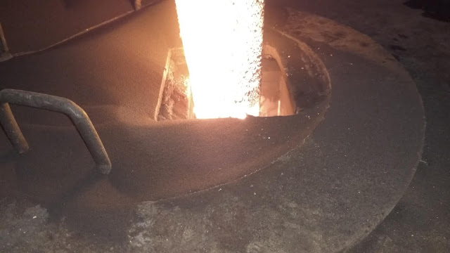
pic below shows one such incident where slag is drained off tundish. it must be noted, steel should not be drained along with slag as this is a heavy loss.
from the pic one must be able to understand how slag (with glass formers like Silica and alumina) form a continuous thread while flowing down the spout WITHOUT BREAKING OR SPLITTING OFF as soon as flowing out.
this slag thread slowly draining off the spout explains a lot, about the high viscosity (around 10times that of liquid steel), that results from interlinking of CaO, silica, alumina and other network forming, slag making molecules that does not allow splitting or breaking off of streams (which normally happens when liquid steel flows.) one can easily identify what overflows is metal or slag with this simple idea in mind.
fly link for tundish change
we do a lot of tundish changes to continue casting uninterrupted even after the life of one tundish is reached, replacing the old tundish with a new one; this process is also called fly tundish.
following pics show the fly link used to form a physical link between old and new billets during tundish change.
these links are designed to link sq.150 size billets in mould.
following pics show the fly link used to form a physical link between old and new billets during tundish change.
these links are designed to link sq.150 size billets in mould.
moulds during installation
this pic shows a set of 5 moulds placed on the oscillating bench of a caster.
what are the specifications should one know about these moulds? well. there is a lottttttttttt. a lot indeed. but a simple look into this image can tell us some basic, ballpark info about this caster. such as, this is a square mould that casts billets continuously; there is this AMLC, and M-EMS; radioactive sources are placed outside the mould body as against some other mould bodies where this source is placed inside; the wider inter-mould-distance shows, this caster is designed to cast much larger sections of billets or rounds (in fact this machine is designed to cast rounds as large as 450mm-dia); these moulds can cast billets in open/close casting modes, which of course needs an oil slit on top of mould.
evident from the absence of fenders in four moulds is that this image was taken during installation.
more on moulds, but later. :-)
mould level detection
level of liquid steel inside mould during casting time is continuously measured, be it open or close casting. depending upon the type of casting, measured level in mould drives the strand speed (in open casting) or, opens/closes the tundish slidegate (in closed casting) so as to meet the casting speed given to the strand withdrawal motors.
this following pics show the physical elements necessary to measure mould level in a continuous casting machine.
in the first pic, at the center is the mould, at the bottom we have the detector, and at the top lies the radioactive source.
the picture above shows the mould of square billet sized 150mm . i created this in visual studio to understand start of casting steps, as the mould gets filled, dummybar withdrawal, filling up of mould to reach the target of around 150mm in detected range, the auto withdrawal start, auto regulation of level to meet the target level.
the pic below shows the schematic mould setup in CCMs; the mould water flow is also shown along with AMLC detection details.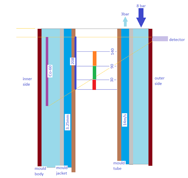
it is a Co-60 radiation source, which normally has a good working life of 6 to 8 years, beyond which there may be some significant loss of radiation that may affect the performance of the AMLC (Auto Mould Level Control system) of casting machines.
gamma radiation from this source reaches the detector (NaI- sodium iodide crystal combined with multipliers and/or amplifiers). this detector is actually a geiger counter that counts the amount of radiation by converting it into pulses.
depending upon the amount of steel that interferes the path of radiation from source to detector, there is a proportionate loss of radiation detected by the detector. higher the interference, higher the loss. the system is calibrated using a solid-steel-calibration-block which simulates full mould level (by attenuating the radiation from reaching the detector), and without that block for empty mould level (this latter allows maximum radiation to reach detector).
once the amount of pulses for full and empty mould are registered, it now becomes an interpolation between these two levels, indirectly proportional to the pulses received for any intermediate levels of liquid steel in mould.
the indepth details shall be looked into but later on another post. :-)
this following pics show the physical elements necessary to measure mould level in a continuous casting machine.
in the first pic, at the center is the mould, at the bottom we have the detector, and at the top lies the radioactive source.
in the second pic, the center has mould, at the right is radioactive source that looks like a round canister, at the left lies the detector. the orange coloured box is the electrical cable connectors housing of Mould-Electro Magnetic Stirrer (M-EMS, not to be confused with Micro ElectroMechanical Systems of electronics industry).
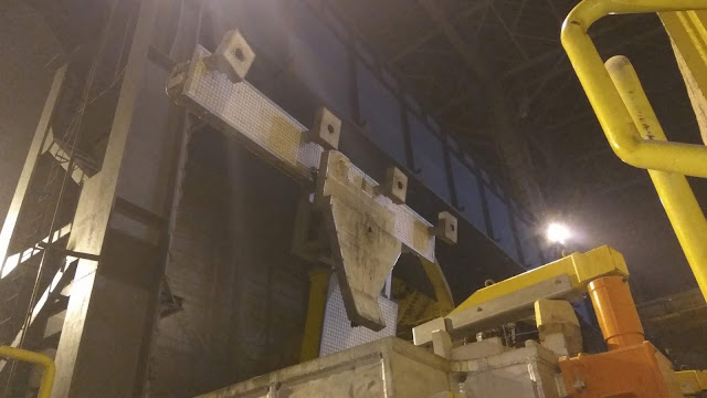
this following, third-pic of this post shows radioactive source from the casters side (while the first shown from secondary metallurgy units' or turret side). radiation warning sign is very much clearly visible in this pic below.
the picture above shows the mould of square billet sized 150mm . i created this in visual studio to understand start of casting steps, as the mould gets filled, dummybar withdrawal, filling up of mould to reach the target of around 150mm in detected range, the auto withdrawal start, auto regulation of level to meet the target level.
the pic below shows the schematic mould setup in CCMs; the mould water flow is also shown along with AMLC detection details.

gamma radiation from this source reaches the detector (NaI- sodium iodide crystal combined with multipliers and/or amplifiers). this detector is actually a geiger counter that counts the amount of radiation by converting it into pulses.
depending upon the amount of steel that interferes the path of radiation from source to detector, there is a proportionate loss of radiation detected by the detector. higher the interference, higher the loss. the system is calibrated using a solid-steel-calibration-block which simulates full mould level (by attenuating the radiation from reaching the detector), and without that block for empty mould level (this latter allows maximum radiation to reach detector).
once the amount of pulses for full and empty mould are registered, it now becomes an interpolation between these two levels, indirectly proportional to the pulses received for any intermediate levels of liquid steel in mould.
the indepth details shall be looked into but later on another post. :-)
ladle turret emergency rotation
there may come a time in a casting floor (indeed we faced, and i used pneumatic rotation twice), when we have uncontrolled flow of liquid steel from ladle (may be due to slidegate through, or ladle lining through or slidegate cylinder closing failure).
during those times, emergency rotation command can be issued to take ladle to the charging position where the liquid steel can be safely dumped into an emergency ladle kept for safety.
sometimes accessing emergency rotation may take a little longer than reaching a pneumatic rotation system provided as an extra safety feature in modern casting platforms.
the following pictures show one such installed in a caster which was not yet commissioned when these pics were taken.
on the left side is the regularly used electrical motor, that has a discbrake mechanism to hold the motor still ( and hence the turret) from rotating when it is expected to stay put.
there is a rotary encoder nearby the planetary gear mechanism that tracks the position of rotation of the turret from zero to 360 degree as the turret turns during ladle changes.
at the bottom is a pneumatic switch which should stay healthy so that the brake can be engaged/disengaged whenever necessary for rotation.
on the right is the pneumatic motor connected to the same shaft that drives the planetary gear mechanism of the turret. the pneumatic motor has two instrument-air (IA) lines attached with it. one for clockwise and the other for anticlockwise rotation.
normally there would be an accumulator tank which stores IA in enough quantity to turn the turret at least 5 to 6 times and that tank is further connected to a regular IA line supply that runs all along the shopfloor.
during those times, emergency rotation command can be issued to take ladle to the charging position where the liquid steel can be safely dumped into an emergency ladle kept for safety.
sometimes accessing emergency rotation may take a little longer than reaching a pneumatic rotation system provided as an extra safety feature in modern casting platforms.
the following pictures show one such installed in a caster which was not yet commissioned when these pics were taken.
there is a rotary encoder nearby the planetary gear mechanism that tracks the position of rotation of the turret from zero to 360 degree as the turret turns during ladle changes.
at the bottom is a pneumatic switch which should stay healthy so that the brake can be engaged/disengaged whenever necessary for rotation.
on the right is the pneumatic motor connected to the same shaft that drives the planetary gear mechanism of the turret. the pneumatic motor has two instrument-air (IA) lines attached with it. one for clockwise and the other for anticlockwise rotation.
normally there would be an accumulator tank which stores IA in enough quantity to turn the turret at least 5 to 6 times and that tank is further connected to a regular IA line supply that runs all along the shopfloor.
Friday, July 20, 2018
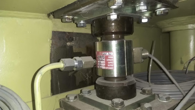
load cells!
load cells!
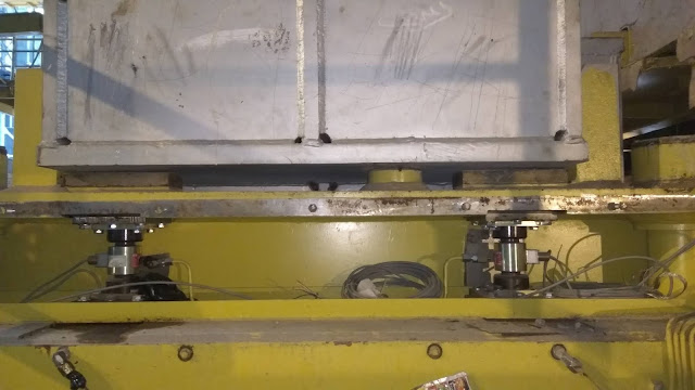
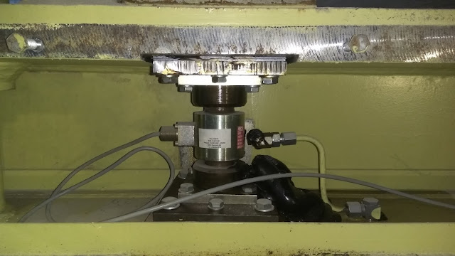
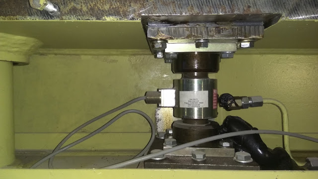
are essential parts for a troublefree casting operation. if they fail, we may either dump a lot slag into tundish (if slag entry is not detected automatically/manually).
there are times when auto tundish regulation failed and led to ladle closures because of improper seating of tundish on loadcells.
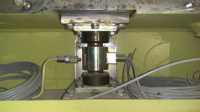
generally there are four load cells placed on the all four corners of a tundish. they must be perfectly levelled so that whenever a tundish is placed on the tundish car, the entire load of the tundish must be equally distributed on to those 4 load cells, each taking 1/4th of the entire tundish load.
if the levelling is not proper, tundish may not sit properly leading to fluctuations and hence troubled casting experience.
here are some pics of load cells in a tundish car. similar load cells are fixed in ladle turret arms too but with a little higher ratings.
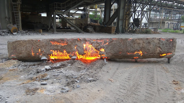
sometimes improper loadcell placement may give huge errors that the shown tundish weight may be much lower than it actually is. sometimes we may end up discarding a lot of metal as tundish skull.
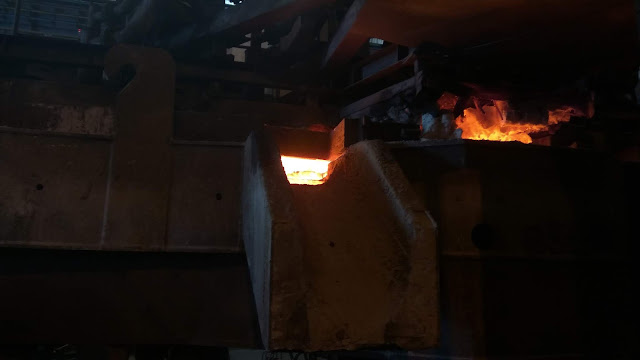
this above pic shows a tundish skull. has a lot of hot steel that shines in bright yellow. the brown covering on the tundish is the spray/working lining of which is made of roughly 70% MgO and 20% Silica.
air-mist spray nozzle.
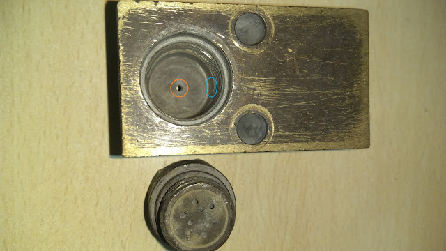
this picture below shows a fullcone air-mist nozzle, which was under user for sometime but has been removed due to choking of the port.
the front cap-block has been removed for easy cleaing and kept by side the side of the nozzle block.
inside that cavity of the cap we can see where the air should come (the whole rounded in orange circle) and how water should enter (the hole rounded in blue ellipse) so that that water can be atomized into mist.
normally the water pressure is around 4 to 8 bars while that of air is around 4 to 6 bars. the volumetric ratio is around 1:30 or 1:40. water flow varies with varying speeds of casting.
tundish preheaters and burner blocks
this following pic shows a tundish preheater after using 6 months from installation.
a simple observation can easily reveal the minor damages on the 3rd and 6th burners, counting from left side. this is the sign of burner holes in tundish covers having a mismatch with those burners. if not those holes are perfectly matched, they may eventually expedite the damage rate of these burners as well as the refractory around it.
they may some time get damaged to such an extent that the broken pieces of burners may fall on the starter tubes of tundishes and collapse them. this would block the flow of steel during start of casting and that strand may be lost without sufficient, proper initial flow.
the following picture shows a tundish under heating in under this preheater; and the overflow spout is clearly visible at the center of the picture. a closer look shows the hole-for-burner in the cover of the tundish too.
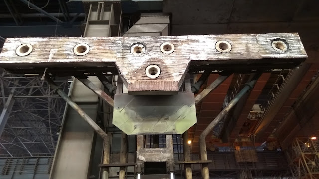
this following pic shows a preheater from another caster where we have 5 strands. bottom right of the image shows the actuator-box (orange colored) the monoblock stopper can also be seen.
an advantage with this preheater is the extended burner blocks. changing these becomes much more easier than those of the previous preheater. (burner block change in the previous preheater takes somewhere around 4 to 6 hours depending on the ease with which old, rusted or weathered bolts of the old broken burners come off.)
since this image was taken before commissioning the stopper arms are not covered with refractory grade glasswool.
Subscribe to:
Posts (Atom)


